Get Polyphase Induction Motors Multiple Choice Questions (MCQ Quiz) with answers and detailed solutions. Download these Free Polyphase Induction Motors MCQ Quiz Pdf and prepare for your upcoming exams Like SSC, Railway, UPSC, State PSC.
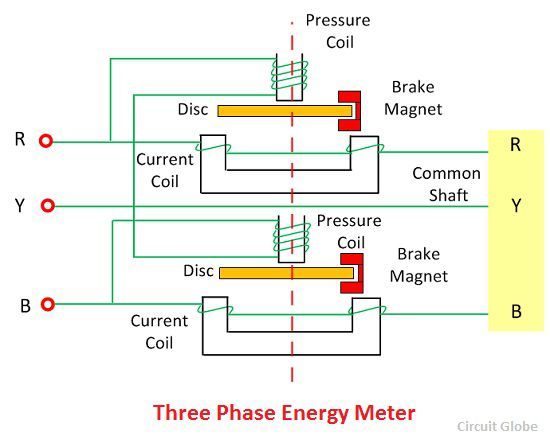
- Type KY wattmeters are electrodynamic type. Polyphase wattmeters may be checked on single phase circuits by testing each element separately,or the current coils may be connected in series and the potential coils in parallel, both elements tested at the same time. Cali bration adjustments are made by changing the.
- SINGLE-PHASE AND POLYPHASE WATTMETERS (TAUT-BAND SUSPENSION) INTRODUCTION These instructions cover the installation of the Types AB-16,-30 j and-40 single-and polyphase wattmeters. The wattmeters are rectangular-pattern, switch-board instruments designed for flush mounting. The moving systems are supported.
- Polyphase Varmeter. The two auto-transformers are used to create the phase shifting (which is necessary for the measurement of reactive power), when connected in open delta configuration. Current coils of both the wattmeter are connected in series with supply line 1 and 3. While pressure coils are connected in parallel as shown in the diagram.
- “Polyphase” means “many phases,” describing a form of AC electrical system where multiple sinusoidal voltages exist that are not in step with each other. The most common form of polyphase AC power in industry is three-phase, but all polyphase systems share similar traits. A good way to understand three-phase AC systems is.
Problems
1.The input power to a 3-phase a.c. motor is measured as 5kW. If the voltage and current to the motor are 400V and 8.6A respectively, determine the power factor of the system?
Power P=5000W,
line voltage VL = 400 V,
line current, IL = 8.6A and
power, P =√3 VLIL cos φ
Hence
power factor = cosφ=P√3VLIL
=5000 √3 (400) (8.6)
=0.839
2.Two wattmeters are connected to measure the input power to a balanced 3-phase load by the two-wattmeter method. If the instrument readings are 8kW and 4kW, determine (a) the total power input and (b) the load power factor.
(a)Total input power,
P=P1 +P2 =8+4=12kW
(b) tan φ =√3(P1 − P2)/(P1 + P2)
=√3 (8 – 4) / (8 + 4)
=√3 (4/12)
=√3(1/3)
= 1/ √3
Hence φ= tan−1 1 √3 =30◦
Power factor= cos φ= cos 30◦ =0.866
3.Two wattmeters connected to a 3-phase motor indicate the total power input to be 12kW. The power factor is 0.6. Determine the readings of each wattmeter.
If the two wattmeters indicate P1 and P2 respectively
Then P1 + P2 = 12kW | ---(1) |
tan φ =√3(P1 − P2)/(P1 + P2)
And power factor=0.6= cos φ.
Angle φ= cos−10.6=53.13◦ and

tan 53.13◦ =1.3333.

Hence
1.3333 =√3(P1 − P2)/12
From which,
P1 − P2 = 12(1.3333) /√3
i.e. P1 −P2 =9.237kW ----(2)
Adding Equations (1) and (2) gives:
2P1 = 21.237
i.e P1 = 21.237/2
= 10.62kW Hence wattmeter 1 reads 10.62kW From Equation (1), wattmeter 2 reads
(12−10.62)=1.38kW
4.Three loads, each of resistance 30, are connected in star to a 415 V, 3-phase supply. Determine
(a) the system phase voltage, (b) the phase current and (c) the line current.
A ‘415 V, 3-phase supply’ means that 415 V is the line voltage, VL
(a) For a star connection, VL =√3Vp Hence phase voltage, Vp = VL/√3
=415 /√3
=239.6 V or 240 V
correct to 3 significant figures
(b) Phase current, Ip = Vp/Rp
=240/30
=8 A
(c)For a star connection, Ip = IL Hence the line current, IL = 8 A
5.Three identical coils, each of resistance 10ohm and inductance 42mH are connected (a) in star and (b) in delta to a 415V, 50 Hz, 3-phase supply. Determine the total power dissipated in each case.
(a) Star connection
Inductive reactance,
XL =2πf L =2π (50) (42×10−3) =13.19
Phase impedance,
Zp =√(R2+XL2)
=√(102 +13.192) =16.55
Line voltage, VL =415 V
And phase voltage,
VP =VL/√3=415/√3=240 V.
Phase current,
Ip =Vp/Zp =240/16.55=14.50 A. Line current,
IL =Ip =14.50 A.
Power factor= cos φ=Rp/Zp =10/16.55 =0.6042 lagging.
Power dissipated,
P =√3VLIL cosφ=√3 (415) (14.50)(0.6042) =6.3kW(Alternatively,
P =3I2R=3(14.50)2(10)=6.3kW)
(b) Delta connection
VL = Vp = 415 V,
Zp = 16.55_, cos φ = 0.6042lagging (from above). Phase current,
Ip =Vp/Zp =415/16.55=25.08A. Line current,
IL =√3Ip =√3(25.08)=43.44A.
Power dissipated,
P =√3VLIL cosφ
=√3 (415)(43.44)(0.6042) = 18.87kW
(Alternatively,
P =3I2R
=3(25.08)2(10) =18.87 kW)
6.A 415V, 3-phase a.c. motor has a power output of 12.75kW and operates at a power factor of 0.77 lagging and with an efficiency of 85 per cent. If the motor is delta-connected, determine (a) the power input, (b) the line current and (c) the phase current.
(a) Efficiency=power output/power input.
Hence
(85/100)=12.750 power input from which, Power input = 12. 750 × 10085
=15 000W or 15Kw
(b)Power, P=√3 VLIL cos φ, hence
Polyphase Wattmeter Pdf File
(c)line current,
IL = P/ √3 (415)(0.77)
=15 000/ √3 (415) (0.77)
=27.10A
(d)For a delta connection, IL =√3 Ip,
Hence
Phase current,Ip = IL/√3
=27.10 /√3
=15.65A
7.A 400V, 3-phase star connected alternator supplies a delta-connected load, each phase of which has a resistance of 30_ and inductive reactance 40_. Calculate (a) the current supplied by the alternator and (b) the output power and the kVA of the alternator, neglecting losses in the line between the alternator and load.
A circuit diagram of the alternator and load is shown in Fig.
(a) Considering the load:
Phase current, Ip =Vp/Zp
Vp =VL for a delta connection,
Hence Vp =400V.
Polyphase Wattmeter Pdf Download
Phase impedance,
Zp =√ (R2+XL2)

=√ (302 +402) =50
Figure
Hence Ip =Vp/Zp =400/50=8A.
For a delta-connection,
Line current, IL =√3 Ip =√3 (8) =13.86 A.
Hence 13.86A is the current supplied by the alternator.
(b) Alternator output power is equal to the power Dissipated by the load
I.e. P =√3 VLIL cos φ, Where cos φ = Rp/Zp = 30/50 = 0.6.
Hence P =√3 (400) (13.86) (0.6) = 5.76kW.
Alternator output kVA,
S=√3 VLIL =√3 (400) (13.86)
9.60 kVA.